CAD/CAM software
What are CAD and CAM systems?
CAD (Computer-Aided Design) and CAM (Computer-Aided Manufacturing) are two interconnected types of software extensively used in various fields of manufacturing, engineering, and design.
What is the main difference between CAD and CAM systems?
The fundamental difference between CAD (Computer-Aided Design) and CAM (Computer-Aided Manufacturing) systems lies in their purpose and functionality:

How do they interact?
CAD (Computer-Aided Design) and CAM (Computer-Aided Manufacturing) systems interact closely and effectively to ensure a seamless process from design to production.

CAM software workflow
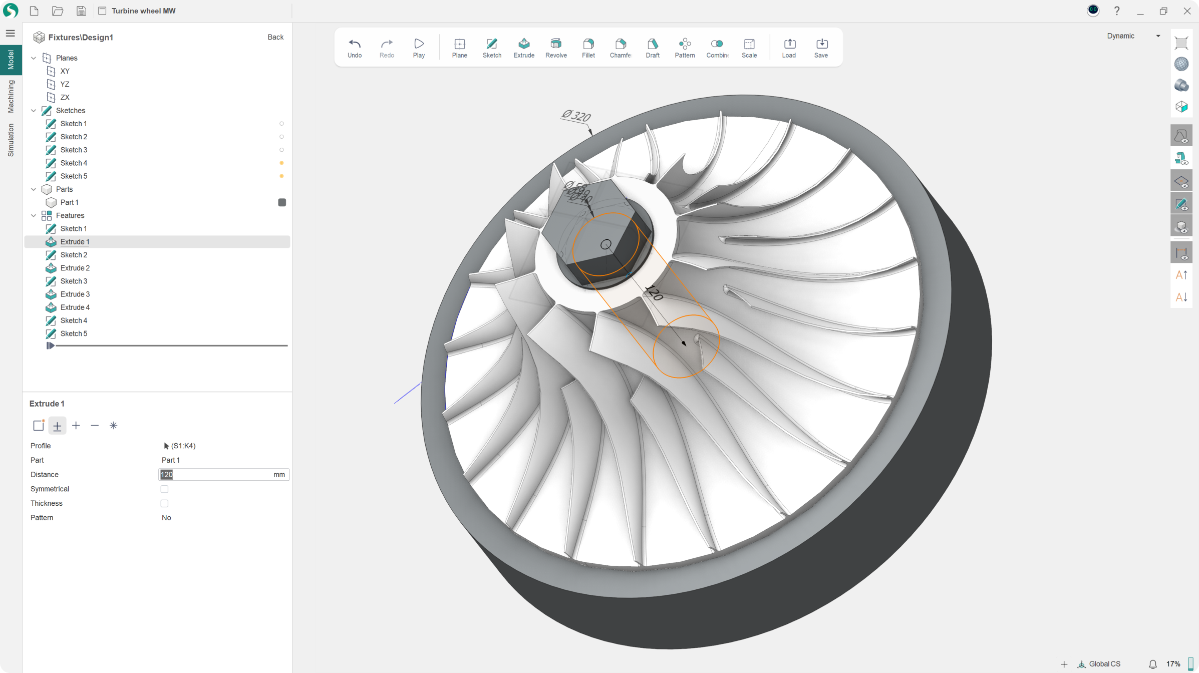
Import a model
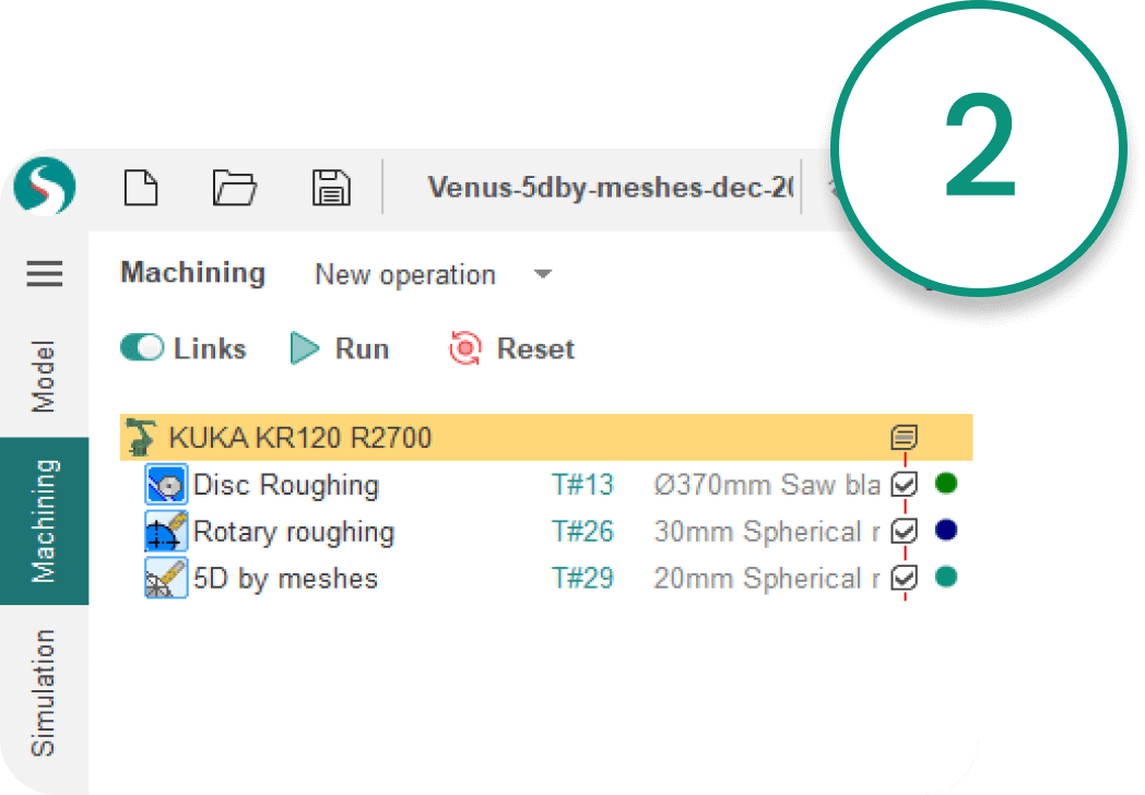
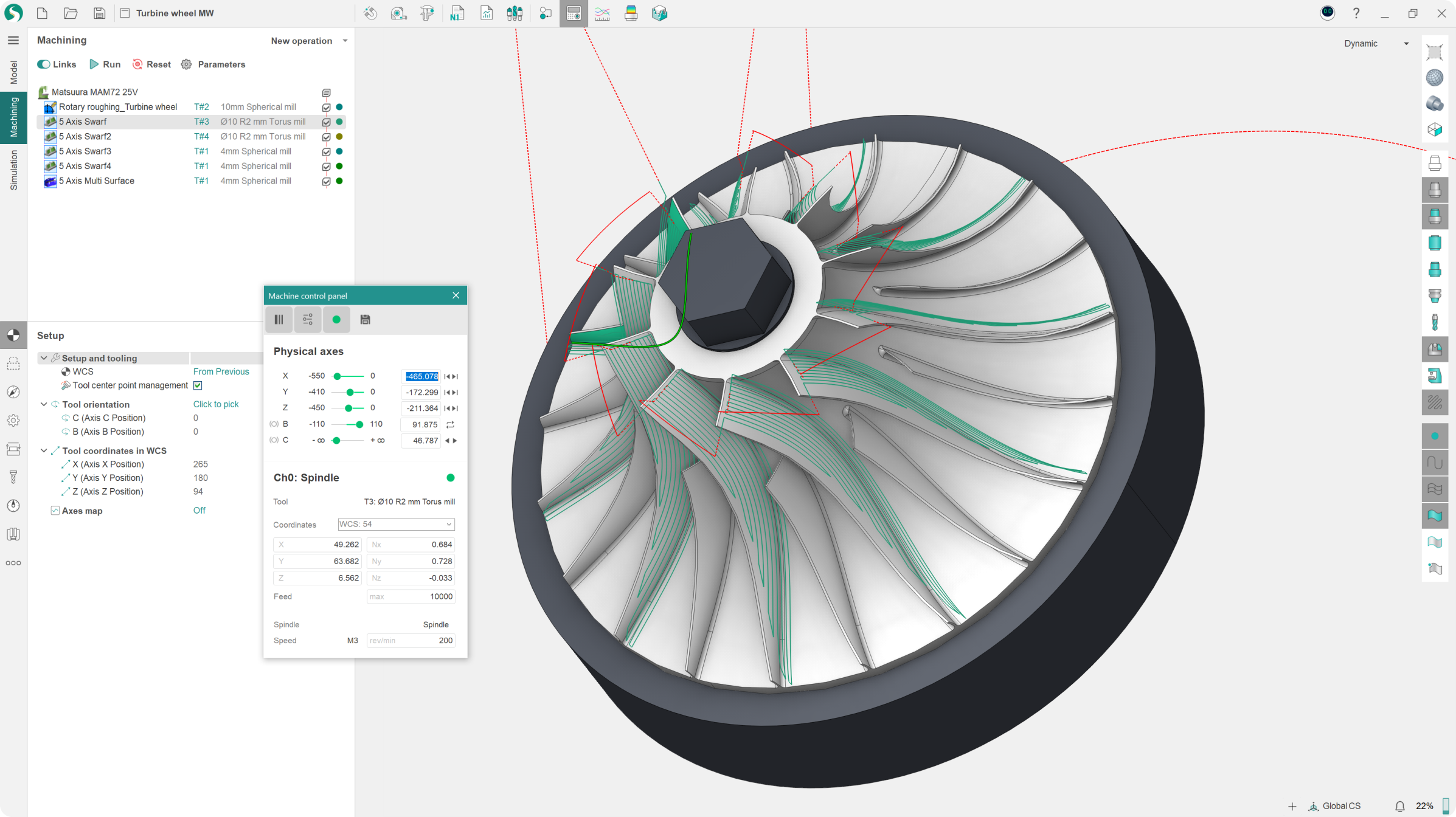
Create the machining process
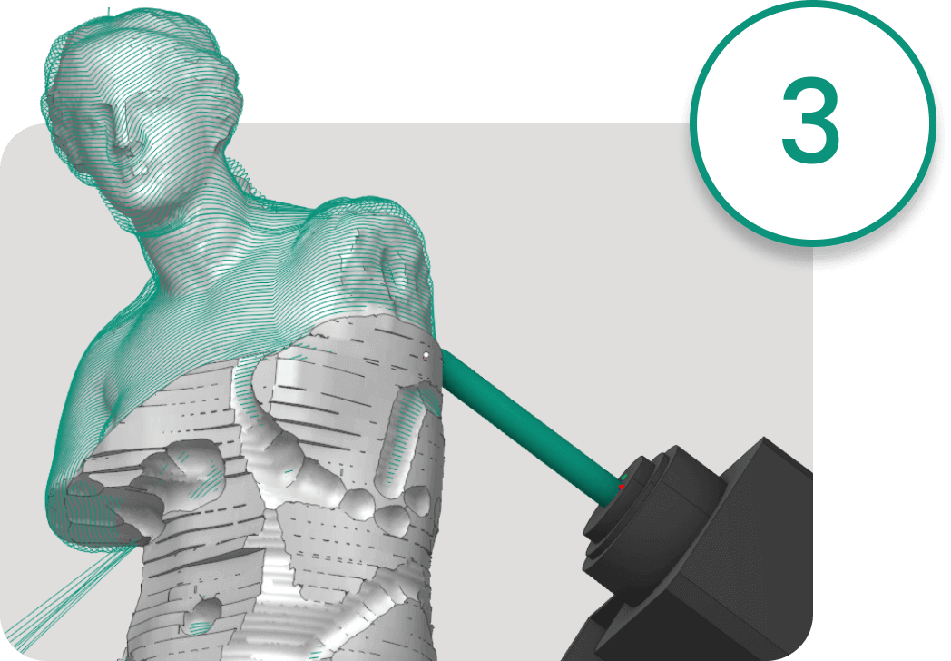
Simulate and verify

Output the code, do the machining
So what is CAD/CAM software?
The term CAD/CAM systems refers to integrated software that combines the functionality of both CAD (Computer-Aided Design) and CAM (Computer-Aided Manufacturing) within a single system. This ensures seamless interaction between design and manufacturing. Here are the key aspects of CAD/CAM systems:
- Integration: In CAD/CAM systems, the design and manufacturing processes are closely linked. This allows users to easily and swiftly move from creating a model to preparing it for production. Integration reduces the likelihood of errors and increases workflow efficiency.
- Efficiency: Since design and manufacturing are managed through one platform, it cuts down on the need for data entry and lets both processes run more efficiently. This speeds up the entire production chain from the initial idea to the finished product.
- Production Optimization: CAD/CAM systems let you make detailed adjustments to manufacturing parameters right from the design environment. This helps you use materials more efficiently, cut down on waste, and get products out the door faster.
- Flexibility: Integrated CAD/CAM systems support various types of manufacturing equipment, including CNC machines, laser and plasma cutters, robotic devices, etc., offering high flexibility in the choice of technologies and equipment for production.
- Applications: CAD/CAM systems are used in many industries, including aerospace, automotive, shipbuilding, dentistry, jewelry making, and many others where high precision and quality of products are required.

What is CAD/CAM software used for?
CAD/CAM systems are used for designing and manufacturing complex parts that require high precision and durability.
CAD/CAM systems automate manufactuing processes, including milling, turning, laser cutting, and 3D printing. This ensures high precision and reduces the rate of defects.
CAD/CAM systems enable rapid prototyping of new products, accelerating the development process and allowing for testing before mass production begins.
CAD/CAM systems make it economically feasible to produce small batches of products or even individual custom orders tailored to the specific needs of a client.
Overall, CAD/CAM systems enhance the quality and efficiency of manufacturing processes, reduce the time spent on design and production, and provide high adaptability to changing market demands and technological innovations.
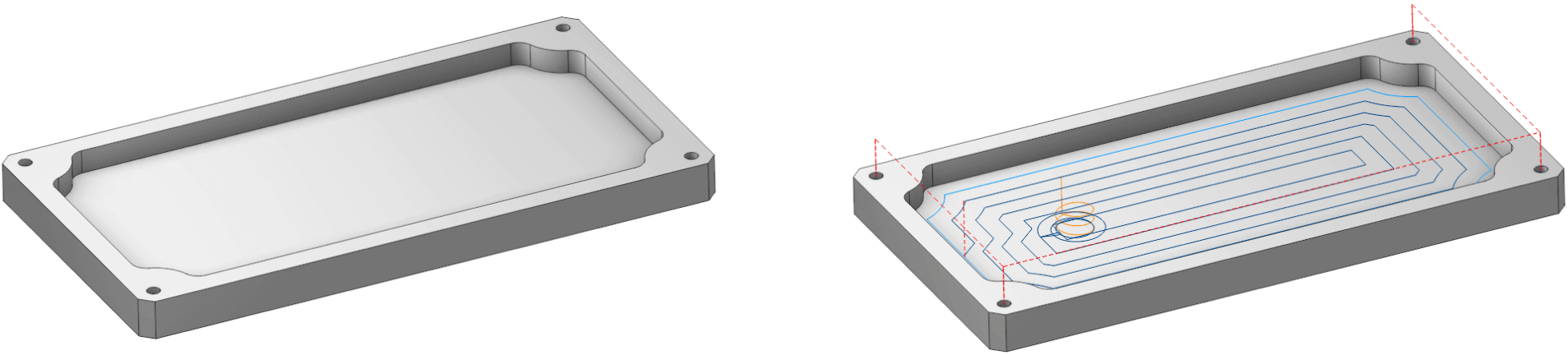
Version 1
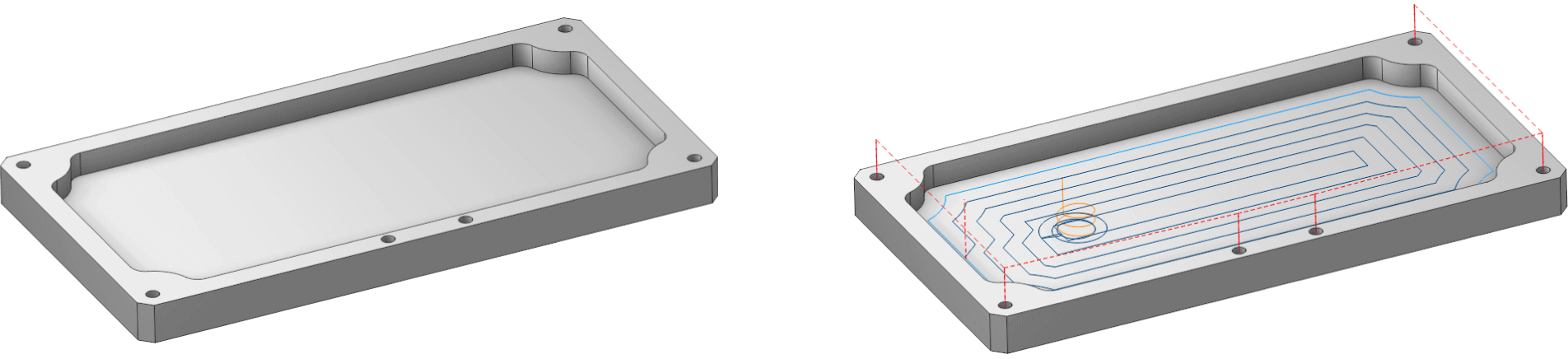
Version 2
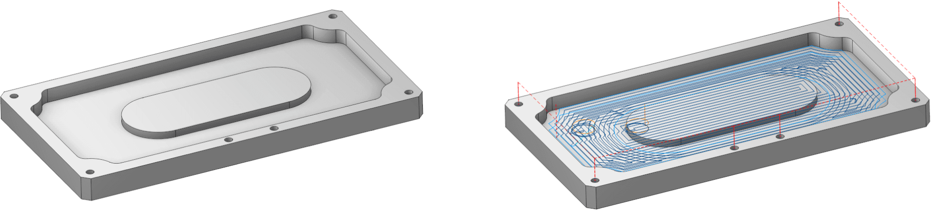
Version 3
What are the benefits of using CAD/CAM software?
- Increased Productivity: Automating design and manufacturing processes with CAD/CAM systems significantly speeds up both processes, reducing the time from concept to product realization.
- Improved Product Quality: Precise modeling and machine control capabilities allow for the production of components with high accuracy and reduced error rates, directly impacting the quality of the final product.
- Cost Reduction: CAD/CAM systems help minimize material waste through optimized cutting and machining processes. Labor costs are also reduced as less time is spent on rework and error correction.
- Flexibility in Design Changes: CAD/CAM software makes it easy to modify designs, adapt to new requirements, and try out new ideas without huge additional costs.
- Rapid Scaling of Production: CAD/CAM tools are great for quickly prototyping and modifying designs, which means you can easily scale up production from small batches to large-scale manufacturing. These advantages make CAD/CAM systems vital for any industry requiring precise and efficient design and manufacturing.
Version 1
Version 2
Version 3
What are the benefits of using CAD/CAM software?
Often, 3D part models imported into a CAM system from third-party CAD systems must be modified to fit the company’s machinery, such as CNC machines and industrial robots. In addition, such refinements may require multiple iterations as the model is transferred from CAD to the CAM system and back.
During these operations, model information can become corrupted and require constant rework. With an integrated CAD/CAM solution, changes to the geometry of the 3D model of the part to be machined can be made in the same environment and no information is lost. This significantly reduces the time it takes to prepare the part for production and approve changes to the design.